FAQ
The Most FAQ DST Gets Asked
Do you sometimes feel confused and overwhelmed by all the drafting terminology? I totally get it.
After all, the drafting industry is undergoing its biggest revamp since the integration of AutoCAD.
As a result, it’s become essential for us to learn and understand many of the new words, phrases, abbreviations and programs. How else will we make this integration as easy as possible?
So, let’s have a look at some of the most FAQ DST gets asked by their clients.
What is meant with 1-7D projects?
1D Project:
- Concept: single line design (sketches)
- Reason for use: quick and easy way to complete design concept (little info on drawing)
- Programs typically used: AutoCad/Hand Sketch
- Concept: double line design concept
- Reason for use: better representation of space requirement. Doesn’t normally take height into consideration (more information than 1D).
- Programs typically used: AutoCat/Revit
- Concept: objects modelled to represent true size and appearance
- Reason for use: best for coordination and giving true representation of site conditions (will provide the most info, depending on use)
- Programs typically used: Revit
- Concept: time
- Reason for use: realistic lead times for manufacturing, ordering and construction phases
- Programs typically used: Revit/Naviswork
- Concept: cost
- Reason for use: a near-true cost of the build at different stages or phases
- Programs typically used: Revit/Naviswork
- Concept: procurement
- Reason for use: shows which services will be working in which area at any given time on site
- Programs typically used: Revit/Naviswork
- Concept: operation
- Reason for use: provides the building manager with information on the life cycle of components within the building (eg lights, fans, equipment)
- Programs typically used: Revit/Naviswork
What is the difference between CAD, REVIT, and NAVISWORKS?
CAD:
- File type: .dwg
- Can create design drawings from
- Can create shop drawings from
- Can be used for 2D coordination
- File type: .rvt
- Can create design drawings from
- Can create shop drawings from
- Can be used for 3D coordination
- Can be used for 2D coordination but will have to export to .dwg
- Typically used for “BIM” projects
- File type: .nwc, .nwf and/or .nwd
- Can run Clash Detection
- Can be used for 3D coordination
- Typically used for “BIM” projects
What is the difference between Purge and Unpurged REVIT models?
Purge Revit Model:
- File size: smaller (eg 60MB)
- Views left in the model: 1 3D view
- Time to get shop drawing produced: longer due to drafting team having to recreate sheets and views that were already created but deleted.
- Cost to do drafting: generally more expensive due to above points
- Reason for sending models like this: most of the time companies send purge models to try and protect “IP” or for security reasons.
- Summary: overall, you want to avoid getting unpurged models as this will impact on both cost and timeframes.
- File size: larger (eg 100MB)
- Sheets left in the model
- Views left in the model
- Text (annotation)
- Time to get shop drawing produced: shorter turnaround as the drafting team will only need to focus on shop drawings, nor recreating a project from scratch.
- Cost to do the drafting: typically cheaper due to the above points
- Reason for sending models like this: mainly to help the shop drawing team and the project overall
- Summary: overall, you want to try and get unpurged models as this will make the project cheaper and quicker to produce shop drawings.
What are the file extensions and what do they mean?
.dwg
- Created in Autocad, Revit & CAMduct
- Used as an overlay for other services
- Can be used in Autocad, Revit & CAMduct
- Created in Revit
- Used for coordination and design, and shop drawing creation
- Can be used in Revit only
- Revit & CAMduct
- Used for coordination between different versions of Revit and CAMduct
- Can be used in Revit and CAMduct
- Created in Revit
- Used for creating NWF files (see Naviswork Breakdown)
- Can be used i Naviswork Manage and Naviswork Simulate
- Created in Navisworks
- Used for sending to clients (can be sent to other services)
- Can be used in Naviswork Manage, Naviswork Simulate, and Naviswork Freedom
- Created in Naviswork
- Used for coordination between other services .nwc and clash detection (see Naviswork breakdown)
- Can be used in Naviswork Manage and Naviswork Simulate
What are the guidelines for Clash Resolution?
Click on the image below for a detailed explanation.

What does LOD mean?
LOD stands for Level Of Development or Level Of Detail and is an acronym used within the industry to explain the level of detail a project will need to achieve to meet the requirements of the client. This is normally outlined within the specification. Depending on which level of LOD is required, it will also govern the cost of the project to ensure all requirement are meet.
Below is a quick break down of what each LOD level represents and what is involved to ensure it meets basic requirements.
LOD 100:
LOD 100:
- Shows the basic representation of the design with the use of either symbols or generic models/elements to depict equipment or fitting locations.
- Will also have minimum detail (maybe sizes of key objects and some equipment names).
- Will have objects such as pipes, ductwork and cable tray drawn with a single line.
- Will allow you to analyse the basic design and to calculate rough costings and/or start to form pricing schedules.
- Has more detail added than a LOD 100 model (few sizes of key objects and equipment names).
- Will have a better representation of objects with approximate sizes, shape, orientation and locations.
- Will have objects such as pipes, ductwork and cable tray most likely drawn in either a single line or double line.
- Will have all detail required to start shop drawing phase (e.g. sizes, equipment names, section, basic schedules, schematics, etc).
- Will be modelled either in 2D or 3D.
- Will be the best to use for pricing & estimating prior to construction/shop drawing commencement.
- May require coordination to be carried out at this time between the services.
- Will have all elements accounted for with either a 3D representation or a detail.
- Will include all Installation and manufacturing information on the drawing/model.
- Will have full coordination carried out between all services.
- Will show the true representation on site after all work is completed.
- Will include all “AS INSTALLED” notes in relation to the element/objects on the drawing.
- Will be used for commissioning and handed over to the client.
- Is only used for facility management proposes.
- Will have Cert elements with information about its life cycle, maintenance requirements, ID numbers, Manufacture, type and any other information the client has requested for.
- Will be used by the building supervisor/maintenance crew.
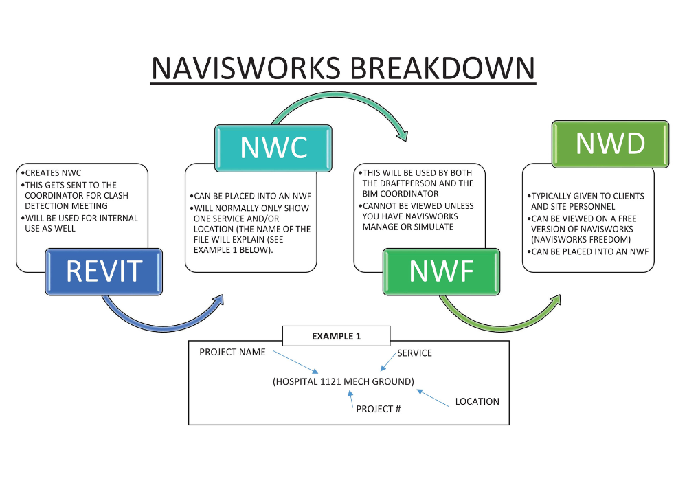
Can you give me a break down of NAVISWORKS?
REVIT:
- Creates NWC.
- Gets sent to the coordinator for Clash Detection Meeting.
- Will be used for internal uses as well.
- Can be placed into an NWF.
- will normally only show one service and/or location (the name of the file will explain it).
- This will be used by both the draftperson and the BIM Coordinator.
- Cannot be viewed unless you have Navisworks manage or simulate.
- Is typically given to clients and site personnel.
- Can be viewed on a free version of Navisworks (Navisworks Freedom).
- Can be placed into an NWF.
What do BIM and FM stand for?
Answer:
BIM stands for Building information modelling and it’s a set of tasks that are supported by various programs and tools including (but not limited to) Revit, Autocad, Navisworks, Archicad and Tekla.
It generates and manages digital representations of physical and functional characteristics of the building/project. In other words, the building is drawn to scale in 3D so that any issues, design flaws, or inefficiencies can be addressed before any work is started on site.
FM stands for Facilities management which is a service that supports the functionality, safety, and sustainability of the building. This is done by storing information in one location so that it can be easily accessed by the end user (the client). Some types of information that are included in a Facilities Management process/program are:
- Maintenance and operations requirements
- Make and model numbers
- Energy management
- Storage space requirements
- Shipping weight
- Etc
Contact DST
Do you have more questions to ask DST? No worries.
Get in touch with us today. We’re looking forward to hearing from you.